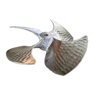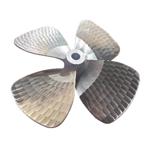
Specific implementation of stainless steel high-speed propeller
The stainless steel high-speed propeller includes a rotating rod 1, a sleeve 2 is sleeved on the side wall of the rotating rod 1, and a plurality of slide bars 5 are installed on the side wall where the rotating rod 1 and the sleeve 2 are connected, and the inner wall of the sleeve 2 A sliding groove matching the sliding strip 5 is provided. A plurality of blades 3 are installed on the side wall of the sleeve 2, and a baffle 6 is installed on the side wall of the rotating rod 1. The baffle 6 and the side wall of the sleeve 2 are mutually When contact is made, the sleeve is sleeved on the side wall of the rotating rod 1 through the cooperation of the sliding strip 5 and the sliding groove and gradually approaches the baffle 6 until the sleeve 2 and the baffle 6 contact each other.
A threaded tube 7 is installed on the end of the rotating rod 1 away from the baffle 6, and a nut 4 is installed on the end of the threaded tube 7 away from the rotating rod 1. The end of the rotating rod 1 away from the baffle 6 is provided with a threaded hole that engages with the threaded tube 7 , Rotating the nut 4 can make the threaded tube 7 move in the threaded hole, and the end of the rotating rod 1 close to the nut 4 is provided with a telescopic device.
The telescopic device includes a telescopic cavity, which communicates with the threaded hole. Two wedge plates 8 are provided in the telescopic cavity. The angle between the inclined surfaces of the two wedge plates 8 and the vertical direction is 45°, and the two wedge plates 8 are opposite to each other. One end penetrates the top wall of the telescopic cavity and extends to the outside of the rotating rod 1. The opposite ends of the two wedge plates 8 are equipped with trapezoidal plates 9 and the angle between the inclined planes of the two trapezoidal plates 9 and the vertical direction is 30°, When the sleeve 2 slides on the rotating rod 1, one end of the sleeve 2 and the inclined surfaces of the two wedge plates 8 contact each other, and gradually squeeze the wedge plates until the sleeve 2 completely passes through the wedge plate 8, and the sleeve 2 The end away from the baffle 6 is in close contact with the side wall of the wedge plate 8, and the wedge plate 8 can fix the casing 2 at this time.
A plurality of telescopic rods are installed on opposite sides of the two trapezoidal plates 9, each telescopic rod includes a sub-rod 10, a female sleeve 11 and a spring 12, and the spring 12 is arranged around the side walls of the sub-rod 10 and the female sleeve 11. , The end of the sub-rod 10 away from the female sleeve 11 is installed on the bottom wall of the trapezoidal plate 9 on the upper side, and the end of the female sleeve 11 away from the sub-rod 10 is installed on the top wall of the trapezoidal plate 9 on the lower side, the sleeve 2 When squeezing the wedge plate 8, the sub-rod 10 can be compressed into the female sleeve 11 and the spring 12 can be squeezed at the same time. When disassembling, only need to rotate the nut 4 to make the threaded tube 7 squeeze the slope of the trapezoidal plate 9 By pressing, the wedge plate 8 returns to the telescopic cavity again, and the binding of the wedge plate 8 to the sleeve 2 is cancelled, and the disassembly of the sleeve 2 is completed, and then it is removed from the rotating rod 1.